
BOURKE CYCLE FORMULA
THE BOURKE CYCLE FORMULA ENHANCED, CLARIFIED, WITH TABLES, FOOTNOTES AND REFERENCES
THE BOURKE ENGINE PROJECT, LLC – ROBERT ZIGLER AND ROGER RICHARD
NOVEMBER 17, 2015
One of the documents that Russell Bourke did not include in the Bourke Engine Documentary was the Bourke Cycle Formula. The original hand written document was extremely difficult to read and had no reference as to when it was written. The Bourke Engine Project, LLC enhanced, clarified and created tables so that the information contained in this important document could be clearly understood and then compared against Russell Bourke’s 30 cid and the 400 cid engine in an attempt to identify when it was created.
As you can see from the comparisons detailed below, this document had to be created and applied to the 400 cid engine (two 200 cubic inch units hooked together) as many of the formula components are not an exact match for the 30 cid engine which was built in the 1950’s. This does not mean that the 30 cid engine did not work, but illustrates the continued refinement of the engine by Russell Bourke. Tables, footnotes and references, especially to the latest development in “homogenous charge, compression ignition (HCCI)” are also included. The format used in this document is:
- The rule is stated and an explanation is provided if necessary
- The rule is compared against the 30 cid engine
- The rule is compared against the 400 cid engine (two 200 cid units hooked together)
RULE – BORE AND STROKE RATIO: The bore and stroke should never be less than 4” bore to 3” stroke ratio: e.g. 24-16, 8-5 ½, 6-4, (has flexibility to meet ring sizes and displacement limits). Table I illustrates the range of bore to stroke ratio’s, in increments of 1/8”, starting at 0.250” stroke and ending with 4.000”stroke.
- RULE APPLIED TO THE 30 CID ENGINE: Russell Bourke’s 30 cid marine engine has a bore of 2.750” and a stroke of 2.350” (bore to stroke ratio of 1.17 to 1). The lower limit in the formula is 1.33 to 1 which means this engine did not meet the rule. However, his 30 cid engine still worked well.
- RULE APPLIED TO THE 400 CID ENGINE (TWO 200 CID UNITS): Russell Bourke’s 200 cid unit had a bore of 5.750” and a stroke of 4.0” (bore to stroke ratio of 1.4375 to 1). The rule states the bore to stroke ratio should fall between 1.33 to 1 and 1.67 to 1. Condition has been met.
RULE – OUTSIDE DIAMETER OF THE CRANK PIN BEARING: The outside diameter of the crank pin bearing must be equal in diameter to the stroke or larger, never less. Never use ball or needle bearings on the crank pin as the violence of the detonation will crush a ball or needle bearing and could kill the operator. Always use a multi-sleeve bearing with the inner and outer races made of Ampco 18.23 with a center race of heat treated steel.
- RULE APPLIED TO THE 30 CID ENGINE: The outside diameter of the crankpin bearing is 2.370” and the stroke of the engine is 2.350”. Rule has been met.
- RULE APPLIED TO THE 200 CID UNITS: The outside diameter of the crank pin bearing is 5.000” and the stroke is 4.000”. Condition met.
RULE – THE COUNTERWEIGHTS NEED TO BE IN THE SAME ARC AS THE CRANK PIN BEARING:
- RULE APPLIED TO THE 30 CID ENGINE: Condition met.
- RULE APPLIED TO THE 200 CID ENGINE: Condition met.
RULE – CRANK PIN O.D. MUST OVERLAP MAIN O.D. AND BOTH MUST BE THE SAME DIAMETER: The crankshaft is the weakest link in the Bourke Engine. In order to strengthen the crankshaft, Russell Bourke recommended that the crank pin outside diameter overlap the main diameter as much as possible. The Bourke Engine Project is specifying the strongest material currently available (4340, vacuum melted, forged billet) for this component. The crank pin O.D. and the main O.D. will be the same diameter.
- RULE APPLIED TO THE 30 CID ENGINE: Crank pin O.D. and main O.D. do not overlap. There is a gap of 0.079” between their O.D.’s and they are not the same diameter. The crank pin diameter is 1.161” and the main diameters are 1.180”. Conditions not met.
- RULE APPLIED TO THE 400 CID ENGINE: Condition met.
RULE – ALL LARGER ENGINES MUST USE MULTI-SLEEVE BEARINGS ON THE MAINS: Russell Bourke recommended that all of his engines use multi-sleeve bearings on the mains to prevent ball bearing failure which destroyed one of his engines.
- RULE APPLIED TO THE 30 CID ENGINE: Ball bearings were used on the mains. Russell Bourke stated he used ball bearings because the perception at the time was that if an engine did not have ball bearings, it was not any good. He recommended the use of multi-sleeve bearings throughout for any Bourke Engine as he had a ball bearing fail and it destroyed one of his engines. Condition not met.
- RULE APPLIED TO THE 400 CID ENGINE: Condition met.
RULE – PORT OPENINGS WILL ALWAYS BE COMPUTED FROM THE DEGREE OF CRANK TRAVEL – INTAKE PORTS: Intake ports are opened by the piston skirt 72 degrees before top dead center and are closed by the piston skirt 72 degrees after top dead center. Intake port hole area is equal to exhaust port hole area. Intake ports, exhaust ports and the lower transfer port holes are all equal in area. Do not use port opening sizes of conventional engines as a guide. The BOURKE operates on much higher pressures and uses much smaller ports with increased efficiency.
- RULE APPLIED TO THE 30 CID ENGINE: The intake ports are opened by the piston skirt 70 degrees before top dead center and are closed by the piston skirt 70 degrees after top dead center. The intake port area of 0.61359 square inches is not equal to the exhaust port area of 0.994 square inches. Conditions not met.
- RULE APPLIED TO THE 400 CID ENGINE: Could not determine from the 2D blueprints when the intake ports opened and closed. The intake port area is equal to the exhaust port area. Area condition has been met.
RULE – PORT OPENINGS WILL ALWAYS BE COMPUTED FROM THE DEGREE OF CRANK TRAVEL – EXHAUST PORTS: Exhaust ports open 55 degrees before bottom dead center by the piston crown and rings and close 55 degrees after bottom dead center by the piston crown and rings. Exhaust port hole size is computed from the stroke by using the ratio for the smallest hole (1 to 0.2188) to the ratio for the largest hole (1 to 0.250). Any exhaust port hole size between these two ratio’s is acceptable (See Table II). Do not use port opening sizes of conventional engines as a guide. The BOURKE operates on much higher pressures and uses much smaller ports with increased efficiency.
- RULE APPLIED TO THE 30 CID ENGINE: The stroke for the 30 cid engine is 2.350 inches. The diameter for the smallest exhaust hole would be 2.350” x 0.2188 = 0.5142”. The diameter for the largest exhaust hole would be 2.350” x 0.2500 = 0.5875”. The actual exhaust port hole size is 0.5625”. Conditions met. Note: there are four (4) exhaust port holes.
- RULE APPLIED TO THE 400 CID ENGINE: Could not determine when the exhaust ports opened and closed from the 2D drawings. Conditions met for the exhaust port hole size.
RULE – PORT OPENINGS WILL ALWAYS BE COMPUTED FROM THE DEGREE OF CRANK TRAVEL – UPPER TRANSFER PORTS: Upper transfer ports open 50 degrees before bottom dead center by the piston crown and rings and close 50 degrees after bottom dead center by the piston crown and rings. Upper transfer port hole size is computed from the stroke by using the ratio for the smallest hole (1 to 0.1875) to the ratio for the largest hole (1 to 0.2000). Any upper transfer port hole size between these two ratio’s is acceptable (see Table II). Do not use port opening sizes of conventional engines as a guide. The BOURKE operates on much higher pressures and uses much smaller ports with increased efficiency. Note: there are four (4) upper transfer port holes, two (2) holes for each segment of the turbulating fins on the piston.
- RULE APPLIED TO THE 30 CID ENGINE: The stroke for the 30 cid engine is 2.350”. The diameter for the smallest upper transfer port hole would be 2.350” x 0.1875 = 0.441”. The diameter for the largest upper transfer port hole would be 2.350” x 0.2000 = 0.470”. The actual upper transfer hole size is 0.4375”. Condition not met for the upper transfer port hole size. Condition was met for the 50 degree opening and closing.
- RULE APPLIED TO THE 400 CID ENGINE: Could not determine when the upper transfer ports opened and closed from the 2D drawings. Conditions met for the upper transfer port hole size.
THE FOLLOWING RULES GIVEN BY RUSSELL BOURKE
IN THE BOURKE CYCLE FORMULA APPLY TO ALL BOURKE ENGINES:
RULE – ROD ENDS MUST BE PARALLEL AND PERFECTLY PERPENDICULAR TO THE ROD SIDES, ROD SIDES MUST BE PERFECTLY PARALLEL AND EQUAL DISTANCE FROM THE CENTERLINE, AND THE ROD SHOE FACE THAT THE BEARING ROLLS ACROSS MUST BE PERFECTLY PERPENDICULAR TO THE ROD SIDES: To withstand the tremendous force of detonation, absolutely precision machining is required. If extremely tight tolerances are not maintained, the misalignment of the components will be magnified many times over, the engine will lose power, economy will drop off, and the engine will wear out prematurely. PRECISION, PRECISION, PRECISION.
RULE – THE PISTON PIN, THE HOLE IN THE SADDLE FOR THE PISTON PIN, THE BASE OF THE SADDLE THAT CONTACTS THE END OF THE ROD, AND THE END OF THE ROD MUST ALL BE PERFECTLY PARALLEL: To withstand the tremendous force of detonation, absolutely precision machining is required. If extremely tight tolerances are not maintained, the misalignment of the components will be magnified many times over, the engine will lose power, economy will drop off, and the engine will wear out prematurely. PRECISION, PRECISION, PRECISION.
RULE – PREVENTING HEAT FROM TRAVELING TO THE SEALS: The saddle and rod must be so constructed to prevent piston heat from traveling to the seals. The hollow rod must have a copper core or be filled with sodium to dissipate heat. The Bourke Engine Project also uses other proprietary methods to dissipate piston heat.
RULE – PISTON:
- Pistons must be split and peaned to have tight cylinder wall contact at all times to permit heat transference to the cylinder wall. If not so split and fitted, the pistons will seize and oil will not be controlled which will make for rough running. Another method to retain piston contact to exhaust and intake face is marcelle rings under bottom ring and ring next to piston pin. Marcelle’s to be only on the lower area, not to extend around piston, and pins in groove to prevent shifting. That portion of piston in contact with the cylinder wall on the exhaust and intake port side must be the same diameter as the cylinder bore when the engine is hot at running temperature. The side opposite the intake and exhaust ports (cylinder circumference being a little more than ½ the diameter) to be undercut to provide clearance for expansion (also to include lands, excepting top land which is undercut as in standard practice). Area at piston pin hole to be relieved through the centerline ½ width of pin hole from the bottom ring groove to equal distance on skirt sides. Piston pins must be fitted so they can be moved with the fingers, having aluminum plugs in the end or felt plugs, which my tests indicate are better, and they aid wall lubrication. Dimples on the face of piston rings are to be desired, with oil grooves and dimples on top of piston in line with the oil hole.
- The above verbiage was taken directly from Russell Bourke’s handwritten document. The piston in the Bourke Engine is the most critical part of the engine as normal piston parameters are not applicable. Years of testing and multiple seizures too numerous to count have finally resulted in a piston that is production ready. The Bourke Engine Project considers all of the technology that went into developing the production ready piston as proprietary information.
RULE – EVEN TEMPERATURE: Route all water and air through case and cylinders to have an even temperature for top performance; this is a MUST.
RULE – INTAKE MANIFOLD: The intake manifold should never be round and should equal 1 ½ or more of the cylinder capacity on the underside of the piston.
RULE – COMPRESSION RATIO: The BOURKE engine can, and should, be run with a compression pressure far higher than is commonly used. All laboratory tests prove a far greater output for the same volume of fuel with a higher compression pressure. The foregoing is known to create detonation, which is the sought for condition in the Bourke engine. Use the highest compression ratio the piston and head design will permit. Higher compression ratios allow for the detonation of leaner mixtures and if the compression ratio is great enough, the BOURKE engine will go into true HCCI (homogenous charge, compression ignition) mode. The higher the compression ratio, the more efficient the BOURKE and conventional engines become. Conventional engines have a limit on how high the compression ratio can be as they are avoiding detonation. The BOURKE engine is only limited by the piston and head design. HCCI Research done at Sandia National Labs by Peter Van Blarigan reveals the following:
- Over 50% increase in thermal efficiency due to nearly constant volume combustion at high compression ratio of 30:1 or greater.
- Maximize thermal efficiency while releasing essentially zero emissions. In order to eliminate the production of nitrogen oxides, the fuel/air mixture must be homogenous and very lean at the time of combustion.
- Capable of operating efficiently on a multitude of fuels.
- Edson (1964) found that even as the compression ratio is increased to 300:1, the thermal efficiency still increases for all the fuels investigated.
- Lean charges have a more favorable specific heat ratio relative to stoichiometric mixtures and this leads to improved cycle thermal efficiencies.
- Generally, higher initial temperatures and higher compression ratios were required to burn more of the fuel to completion. Restricting the exhaust on a BOURKE engine will effectively increase the compression ratio, the engine speed will increase and the engine will run more efficiently (Brake Specific Fuel Consumption expressed as pounds of fuel used per horsepower hour). This claim is made by Russell Bourke and is yet to be verified by The Bourke Engine Project, LLC. The research done on HCCI by Mr. Van Blarigan would seem to validate this claim.
RULE – TURBULATING FINS ON THE PISTON: Turbulating fins on piston permit supercharging of the open ported cylinder without fuel sweep out. They put the fresh air/fuel mixture into cyclonic motion in the top of the cylinder.
RULE – CYLINDER HEAD MUST BE DOMED: The cylinder head must be domed without any break in contour as gas flow would be upset.
RULE – EXHAUST PORTS: Exhaust ports should always be up.
RULE – OIL LINE AND HOLE: Oil line in position between the intake ports and exhaust ports on the top of the cylinder and the hole into the cylinder should register between the top ring and the second ring.
RULE – CYLINDERS: Cylinders should always be parallel with the horizon.
RULE – MULTI-CYLINDER ENGINES: For smoothest operation and greatest horsepower per pound of fuel in multi-cylinder engines, ½ of all cylinders fire at one time to produce an impulse every 180°.
RULE – DETONATION: The BOURKE engine operates on the theory of an induced detonation which can only be produced with a high RPM, extreme high compression pressure and up to 90° spark advance (if you are using spark ignition) with an extremely lean mixture. Cylinder head without water jacket is to be preferred for maximum performance.
RULE – PORT SPACING BETWEEN THE PORTS ON THE TOP OF THE CYLINDER (INTAKE AND EXHAUST) AND THE PORTS ON THE BOTTOM OF THE CYLINDER (UPPER AND LOWER TRANSFER PORTS): Exhaust ports and upper transfer ports to be 1/3 of the cylinder circumference (exhaust ports 1/3, upper transfer ports 1/3). The lands between the exhaust ports (4 holes) and the upper transfer ports (4 holes) is equal to 1/6 of cylinder circumference on each side. The intake ports (2 holes on the 30 cid engine) are on both sides of the oil line. The triangular lower transfer ports have two (2) holes lined up on the window in the piston skirt when the piston is at bottom dead center and one (1) hole centered further down in the cylinder.
RULE – NO GASKETS: Gaskets are to be avoided for more than one reason; makes alignment impossible to maintain and prevents free circulation of temperature. A constant temperature throughout the engine is essential to prevent distortion which shortens engine life by wear and breakage. Safe-door facing procedures, the use of alignment dowels and the extensive use of “O” rings make all alignment and the sealing of all parts positive.
RULE – ROD BUSHINGS: Rod bushings should have circular grooves to aid in oil control and a recess in the top for a “C” ring or leather back-up ring to prevent blow down. Leather seals have proved superior to synthetic as they are always oiled, the synthetic seals will sometimes dry and turn inside out.
RULE – OIL LEVEL: Oil level should be kept to center or a little below center, never above, unless an area is provided for it to be when the engine is in operation (reserve supply). The oiling system as designed is fool proof and any change would not improve it, but could be disastrous. An oiling failure is impossible as it is now designed. The addition of a pump has proved tragic as a pump failure totally destroyed an engine. A means to permit breathing in the case to handle expansion and contraction must be provided.
RULE – PISTON SPEED:
- A piston speed below 1,500 feet per minute (fpm) should be avoided in any engine if long life and economy is to be enjoyed, as a low foot per minute piston travel consumes excessive fuel (i.e. idle or lugging). The latent forces that can be liberated under the Bourke formula require that piston speeds should never be under 1,500 fpm if full advantage of the inherent economy and potential of the Bourke formula is to be realized. This will be readily understood when the chemistry of the combustion cycle is studied and checked against the findings and formulas of the famous engineers, scientists and investigators of bygone years as detailed in their original publications and The Bourke Engine Documentary. These findings have been strengthened by all of the recent research into HCCI.
- HCCI is currently considered to be the “Holy Grail” for internal combustion engines and research by national laboratories and universities is ongoing. The Bourke Engine Project has reviewed many of the current studies and has found that the findings and formulas of those famous engineers, scientists and investigators of bygone years is being “re-discovered” and is now being called HCCI.
RULE – BOURKE CYCLE OF COMBUSTION: For a successful Bourke-cycle of combustion, the following, in order, must be obtained:
- A violent induction and transfer of an extremely lean air-fuel mixture, heat, and a partial vacuum all work together to reduce the liquid fuel to a vapor (atomic particles). Carbon in the fuel triggers the chemical change, and in the process of combustion, hydrogen from the fuel combines with the oxygen from the air when the temperature rises over 1,800 degrees F. The hydrogen/oxygen reaction is triggered by the rising temperature and pressure from the burning carbon, and the compression of a burning charge creates a controlled detonation (4,000 to 5,000 feet per second) forming water vapor and carbon dioxide.
- Detonation occurs very rapidly (4,000 to 5,000 feet per second) and the flame has died at top dead center (TDC) before the piston starts on the power stroke. The piston is not moved on its power stroke by the expansion of the flame as in conventional engines, but by a timed shock that imparts kinetic energy to the piston/rod/yoke plate assembly (as does the powder to a projectile from a gun) thereby instantly storing most of the forces into a moving mass which in turn transfers most of its kinetic energy to the crankshaft over 135 degrees of crankshaft travel –flat torque. There is less heat loss to the cylinder walls as the cylinders are not bathed in flame as in conventional engines and since the flame has died at top dead center, the rapidly expanding exhaust gasses cool (refrigeration cycle – around 200 degrees F exhaust gas temperature – fuel dependant).
- Not all of the kinetic energy stored in the piston/rod/yoke plate assembly is utilized by the crankshaft as there must be a residual amount left to allow the HCCI/detonation process occurring in the opposed cylinder to cushion and stop the piston/rod/yoke plate assembly as the crank pin bearing rolls across the face of the rod. There are no cushioning or stopping forces imposed on the crankshaft, it simply floats in the box that is formed by the rods and yoke plates. All of the cushioning and stopping forces are absorbed within the piston/rod/and yoke plate assembly.
RULE – CLEARANCES: With the exception of the pistons, all clearances to be standard for comparable devices. The yoke plates are the only part of the engine that has a desire to rupture at extreme speeds, so a step in the plate, locating dowels, or body fitting bolts must be used to prevent sheering.
RULE – CONTROL OF ENGINE SPEED: Control of engine speed can be done by spark alone, by spark and carburetor throttle, by exhaust throttle, by exhaust and carburetor throttle, and by exhaust throttle, carburetor throttle and spark.
RULE – FLYWHEEL: Flywheel should never be on opposite end from power take off, as the power will be stored in the wheel and when absorbed at other end, a winding action takes place through the crank pin and will break crank web nearest the flywheel. This cannot happen with flywheel between engine and load as then resistance and loading is one directional.
RULE – ACCURATE WORK: One of the most important steps, which is not necessarily part of the formula, but if not religiously followed, can render the formula worthless, and that is accurate work; making all surfaces flat and all cooperating faces parallel or at 90 degrees, for even the slightest variance will assemble as a curve causing binding, heat and excessive wear and rough operation will result. PRECISION, PRECISION, PRECISION.
RULE – CREDITS: Much of the credit for the successful development of the Bourke Cycle is owed to the eminent scientists, engineers and investigators of a past century, among them Sir Humphrey Davy, Professor Bunson, Mallard and Le Chatelier, Gay-Lussac, Dulungand Petit, Beau De Rochas, Sir Dugald Clerk, Professor Rankine, Boyle, Joule’, Berthalot and Wieille, Sir Fredric Abel, Favre and Siberian, Professor Andrews and others (see the Bourke Engine Documentary).
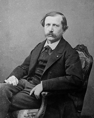
Pierre Eugène Marcellin Berthelot was a French chemist and politician noted for the Thomsen–Berthelot principle of thermochemistry. He synthesized many organic compounds from inorganic substances providing a large amount of counter-evidence to the theory that organic compounds required organisms in their synthesis. He was considered “one of the most famous chemists in the world”.
He gave all his discoveries not only to the French government but to humanity. Berthelot stated the discovery of the explosive wave (detonation) was of no interest to the design engineer because no known engine could withstand such a violent force. Russell Bourke designed his engine to utilize the power of detonation.
Born: October 25, 1827, Paris, France
Died: March 18, 1907, Paris, France
Source: Wikipedia and Bourke Engine Documentary

Global Warming
The chart shows the increase in global average temperature from 1850 to 2018.
Source: Berkeley Earth
Carbon Dioxide In Our Atmosphere
Read all of the scientific reports!!!!!! We are at 415 parts per million, more than anytime in the last 800,000 years. The Bourke Engine using fuel from algae for all transportation and distributive power generation will reduce our carbon footprint for these activities by AT LEAST 85%.


WAKE UP WORLD, WE ARE KILLING OUR PLANET!!!!
2019 – Was the Second Hottest Year on Record!!!!
Global Ocean Acidification
As our oceans absorb excess carbon dioxide, the carbon dioxide reacts with the sea water forming carbonic acid which is changing the pH of our oceans making them more acidic. Research is ongoing as to how the increased acidic level of our oceans is affecting corals and marine life.
Source: IPCC 2007

©2019 Copyright Bourke Engine Project, LLC
All Rights Reserved. All of the information contained within this website can be used, with permission, by any other website providing that the requesting party agrees to the terms and conditions as described in the PERMISSION FORM.
© Copyright 2019-2023 Designed by Lynn
